Billet Specialties, Inc. 500 Shawmut Avenue La Grange, Illinois 60526 PH 800.245.5382 Fax 708.588.7181 www.billetspecialties.com
1. Remove existing gas pedal assembly from vehicle and clear floor area where new pedal is to be mounted.
2. Using the template provided, place the pedal and template on the floor locating a proper mounting position
for the pedal. The bottom of the pedal should be parallel with the floor.
Things To Consider:
• Make sure to mount the pedal in a comfortable position.
• Check for obstructions both inside and outside of the vehicle.
• Check for items such as exhaust, fuel/brake lines, or steering components that may interfere with the
operation of the pedal and linkage.
3. Once a mounting position has been established, tape the paper template to the floor. Using a center
punch mark the four mounting holes and drill holes with a 13/64” bit. Using the throttle cable bracket check
again for any obstructions outside the vehicle.
4. Using the paper template scribe the rectangular arm hole to the floor. It’s recommended to drill 13/64”
holes at each of the four corners of the rectangle and cut between holes and remove material.
5. Re-install floor covering & cut covering to match rectangle hole in floor. Install pedal assembly so that the
gas pedal is at the proper angle and cable arm is at the top of its travel. The Billet Specialties “B-Logo”
located on the cable arm should face the driver side of the vehicle and the spline side of the shaft should
be towards the passenger side. The cable arm assembly should move freely without binding or obstruction.
6. Install throttle cable (not included) per the manufacturers instructions. A 36” cable will fit most
applications.
Making Adjustments
• The floor mount pedal offers adjustment after assembly for: Pedal Angle, Cable Arm Angle, and
allowable travel (travel stops are on cable arm).
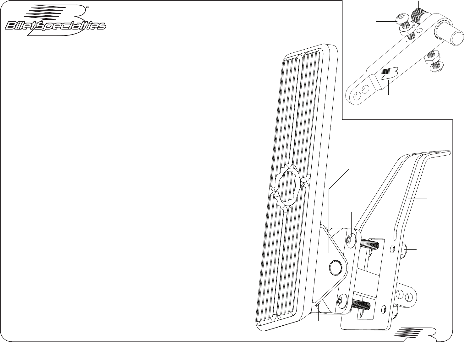
• Pedal & cable arm angle can be adjusted after assembly by removing the spline side [A] of the pedal
bracket, Fig 1. Cable arm must be at the top to ensure full travel of arm and allow for full throttle
operation.
At Idle Adjustment (Top Screw): Carburetor/throttle body linkage should be resting at stop. Throttle
cable should have slight slack at idle position. Tighten jam nut firmly.
Wide Open Adjustment (Bottom Screw): When carburetor/throttle body is at wide open throttle, adjust
bottom screw to just be in contact with pedal pivot housing. Tighten jam nut firmly.
Important: Prior to operating vehicle, check pedal travel for any binding or sticking. Check that
linkage is at full rest at idle and wide open throttle is possible. If in any way there is binding or sticking
on return from wide open throttle re-check installation before driving vehicle.
Tools Required:
1/8” Allen Wrench
5/32” Allen Wrench
3/8” Socket & Wrench
#199270 / #199275 - Floor Mount Gas Pedal
10-32 x 3/4”
Button Head
Cap Screw
10-32 x 3/8”
Socket Head
Cap Screw
[A] Remove This Side
For Angle Adjustment
Spline Towards
Passenger Side
Starting
Travel Stop
Ending Travel Stop
B-Logo Towards
Driver Side
Figure 1: Cable Arm Assembly
10-32 Locking
Hex Nut
Throttle
Cable
Bracket
 (1 pages)
 Manymanuals.com
 Manymanuals.de
 Manymanuals.fr
 Manymanuals.it
 Manymanuals.pl
 Manymanuals.cz
 Manymanuals.es
 Manymanuals-pt.com
Commentaires sur ces manuels